Generation and Measurement Timing
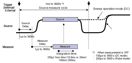
Source measure cycle (source & measure at 1 ms minimum)
As shown in the figure below, the GS610 is capable of synchronizing the generation and measurement at any operation mode. Generation is started after a source delay with respect to an internal/external trigger. Then, after the time it takes for the source level to stabilize (measure delay) the measurement is carried out over a given integration time. This function is necessary when making measurements by waiting for the load response after applying a pulse. The source measure cycle is the minimum unit for signal generation and measurement. The source/measurement operation (source measurement cycle) on the GS610 is 1 ms minimum.
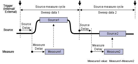
Difference measurement using the sweep operation
The sweep operation can be used to make two measurements, then the difference between the two measurements can be determined. When the source value of sweep data 1 is established, the first measurement is carried out. Then, when the source value of sweep data 2 is established, the second measurement is carried out. The difference is determined by subtracting the value of the second measurement from that of the first measurement. By carrying out the two measurements within a short time, highly accurate measurements are possible with the effects of offset fluctuation cancelled. In addition, by applying a voltage with equal magnitude but opposite in polarity (source 1 = -1× source 2), the effects of offset error caused by the thermo electromotive force at the junction can be cancelled.
Zero Generation Function of Voltage and Current
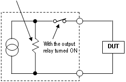
The zero generation function of the GS610 enables the generation of the voltage/current zero value as well as the switching of the output condition between high and low impedance. In the zero generation condition, the voltage application or current supply to the load can be stopped with the output relay turned ON. This function avoids the problems of chattering and contact life of the output relay and reduces the ON/OFF operation time of the output.
Zero generation of voltage
- Low impedance: The current limiter is set to the specified value.
- High impedance: The current limiter is set to 0.5% of the range.
Zero generation of current
- Low impedance: The voltage limiter is set to 0.5% of the range.
- High impedance: The voltage limiter is set to the specified value.
External Input/Output and Synchronized Operation
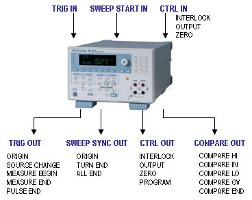
The GS610 has various external input/output connectors. Signals such as the trigger input/output indicating the timing of generation and measurement, the output relay ON/OFF control signal, the zero generation ON/OFF control signal, and the comparator judgment result output can be input/output from the BNC and multi-core connectors. In addition, multiple GS610s can be synchronized by simply connecting the trigger output of a GS610 to the trigger input of another GS610 using a BNC cable.
(For the external view of the connector type, see the "Rear Panel" section on page 7.)
|
Signal Name |
Function |
|
TRIG IN |
TRIG input |
|
SWEEP START IN |
Sweep start input |
CTRL IN |
INTERLOCK |
Interlock input |
|
OUTPUT |
Relay control input |
|
ZERO |
Zero generation control input |
|
TRIG OUT |
ORIGIN |
Trigger output |
|
SOURCE CHANGE |
Source change timing output |
|
MEASURE BEGIN |
Measure start timing output |
|
MEASURE END |
Measure end timing output |
|
PULSE END |
Pulse falling edge timing output |
SWEEP SYNC OUT |
ORIGIN |
Sweep synchronization output |
|
TURN END |
Sweep 1 turn end timing output |
|
ALL END |
Sweep all end timing output |
CTRL OUT |
INTERLOCK |
Interlock through output |
|
OUTPUT |
Relay status output |
|
ZERO |
Zero generation status output |
|
PROGRAM |
Programmable output |
|
COMPARE HI |
Comparison result output HIGH |
|
COMPARE IN |
Comparison result output IN |
|
COMPARE LO |
Comparison result output LOW |
|
COMPARE OV |
Comparison result output OVERRANGE |
|
COMPARE END |
Compare END |
Easy File Operation with the USB Storage Function
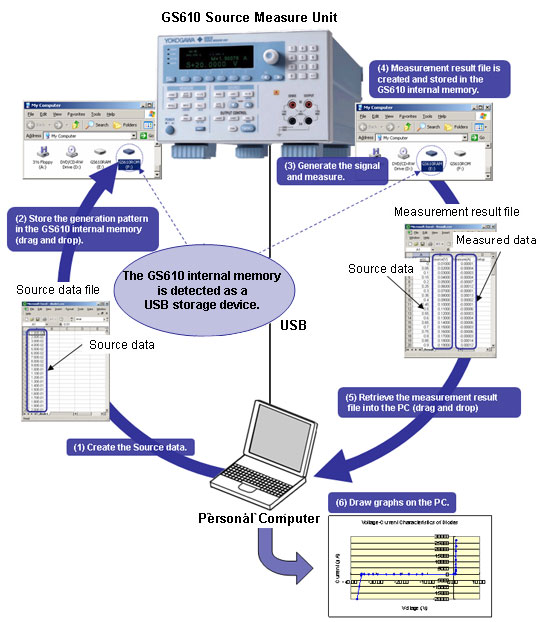
When the GS610 Source Measure Unit is connected to a PC via the USB, the PC detects the GS610 internal memory as a USB storage device. A pattern file can easily be stored in the GS610 internal memory by creating the GS610 generation pattern on a general-purpose worksheet application (1) and dragging and dropping the pattern file (2). The GS610 sweeps the voltage or current levels according to the generation pattern that is written in this file, measures the load current or load voltage at the appropriate points (3), and stores the results to the GS610 internal memory (4). There is absolutely no cumbersome programming or installation of dedicated software programs required (5) and (6).
User-Defined Computation Function
User-defined computation can be performed on the GS610 by combining dedicated operators. It can be used to carry out linear conversion of measured values, compute the power, compute the next generated value from the current measured value, and perform real-time computation of generated data using expressions. The expression is created using a text editor on your PC and stored to the GS610 internal memory via the USB.
Ethernet Interface (/C10 Option)
Remote control and file transfer can be carried out over the network by installing the Ethernet Interface (/C10 option).
Web Server
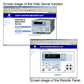
The GS610 connected via the Ethernet interface can be controlled from Internet Explorer.
-
Remote control
Displays a front panel image of the GS610 on the browser with which the GS610 can be remotely controlled.
-
File transfer
The GS610 internal memory can be handled as a PC file server. The output pattern can be transferred to the GS610 internal memory, or the measurement result data can be loaded in the PC.
|
 |
Command control function
The GS610 can be controlled using commands similar to GP-IB or RS232 commands. Up to five clients can connect to the GS610. |
Rear Panel
-
Trigger/sweep/control input (BNC connector)
Select trigger input, sweep start input, or control input.
-
Trigger/sweep/control output (BNC connector)
Select trigger output, sweep start output, or control output.
-
GP-IB
An interface used to remotely control the GS610 from a PC (IEEE 488 compliant).
-
External input/output
Synchronization control signal with other devices and comparator judgment result output.
-
Ethernet (/C10 option)
Complies with 100BASE-TX/10BASE-T. Can be used to carry out FTP file transfer.
-
USB-PC connection
Used to connect to a PC and enable the GS610 internal memory to operate as a USB storage device.