Capture and record detailed waveforms from milliseconds up to months
A ScopeCorder provides a wide variety of unique acquisition features to handle small or large amounts of data. Therefore it can perform multi-channel measurements for longer measurement periods while still being able to precisely capture transient events with the highest detail.
Reduce time spend on fault finding or transient analysis - simple & enhanced triggers
Having the possibility to set individual triggers on multiple channels provides the power to investigate what causes a particular transient event. Moreover, the availability of a large acquisition memory, and thus longer measurement time, helps the analysis of the effect of such an event on other parts of the application.
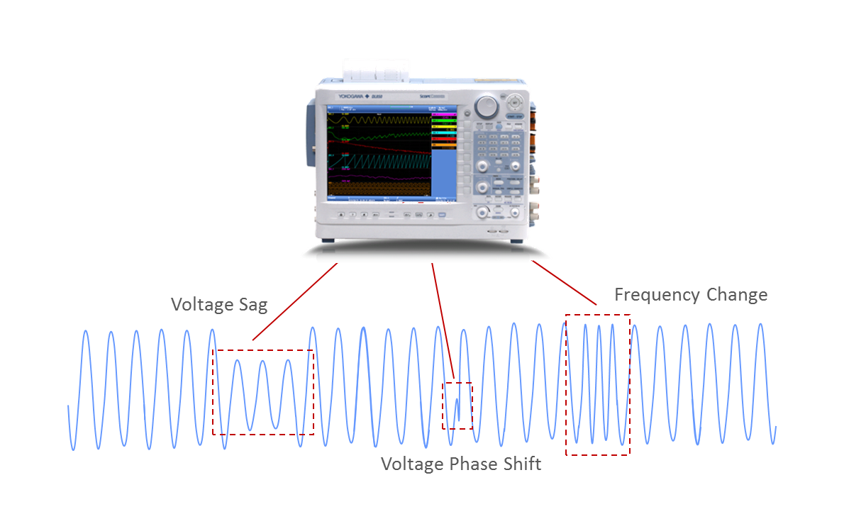
Wave Window Trigger
The ideal trigger for AC power line monitoring. Easily capture voltage sags, interfering impulses, phase shifts or drop outs.
Action on trigger
Leave a ScopeCorder unattended and automatically save the waveform to a file or send an email for notification of a trigger event.
Capture High-Speed Transients During Long Term Recording - Dual capture
To visualize long term trends for durability testing, data is typically acquired at lower speed sample rates. On the other hand, suddenly-occurring transitional phenomena have to be captured at high-speed sample rates and detail to be able to investigate the event. The "Dual Capture" function uniquely resolves these conflicting requirements by recording at two different sampling rates.
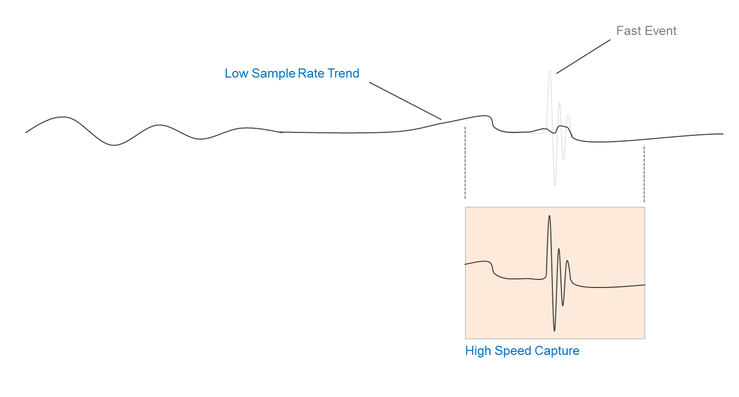
Set waveform triggers and capture 5,000 high-speed transient events at sample rates up to 100 MS/s, while at the same time continuously record trend measurements at up to 100kS/s.
Recall waveform events - History Memory
When an abnormal phenomenon is spotted during a repetitive high speed measurement, the anomaly has often already disappeared from the screen by the time the measurement is stopped. With a ScopeCorder the "History" function is always active and automatically divides the available acquisition memory in up to 5,000 "history waveforms".
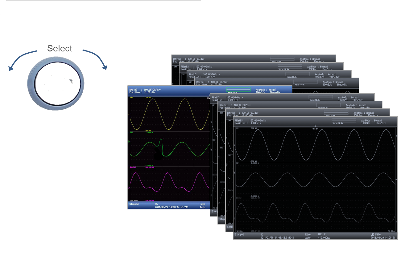
These history records are easily accessible and can be displayed simultaneously after measurement is stopped. Using condition-based searches inside the history memory, users can quickly isolate individual waveforms records. Once the required waveforms have been identified they can be used for further analysis.
Cursor Measurement
Using cursors is a quick and easy method to measure waveform parameters on the screen. Available cursors are horizontal, vertical, marker, degree or combined horizontal & vertical.
Automatic Waveform Parameter Measurement
The parameter measure function is the most precise method for automatically calculating any or all of the 28 different waveform parameters such as, amplitude, peak to peak values, RMS, rise time, frequency and more.The internal time clock (date and time) can be synchronized and adjusted across multiple units. Applications are likely to include synchronizing the ScopeCorder at a windmill farm, finding faults in power grids, and more.
Cycle Statistics
With this powerful analysis function, the ScopeCorder measures selected parameters individually for each waveform cycle and provides statistical information which can easily be saved to a file. By selecting maximum or minimum values from the results, the instrument can automatically zoom into the selected waveform cycle for further analysis, potentially saving additional data analysis time.
Real-time hard disk recording
Use a ScopeCorder as a measurement platform for simple durability testing up to 200 days. Realtime hard disk recording enables measurement data to be streamed directly to either a built-in hard drive (/HD0 option) or via the eSATA interface (/HD1 option) to an external hard drive.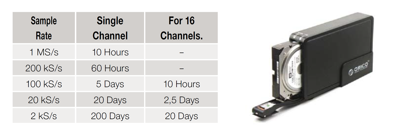
Measurement examples to internal or external Hard Disk
Continuous PC based data acquisition - ScopeCorder Acquisition Software
Especially for longer duration or surveillance testing the ScopeCorder comes with an easy to setup acquisition software. The software enables continuous data recording to a PC hard drive. When using the software in free run mode there are virtually no restrictions in recording time and/or file size. Just click the start button to immediately start measurements!

The Setup Wizard Makes It Easy
Guided by four screens, the Setup Wizard easily guides you through the necessary settings for configuring the acquisition system such as measurement settings, data save and display options.
Downloada free copy of the ScopeCorder Acquisition Software.
GPS Time Synchronization
The ScopeCorders internal clock and the sampling clock can be time synchronized with a GPS clock reference using the /C20 or /C30 option. This allows multiple units to be synchronised in order to combine measurements from different remote locations with most accurate timing. Applications are likely to include synchronising the ScopeCorder measurements at a windmill farm, finding faults in power grids and railway applications. Measurement files from multiple ScopeCorder units can be merged into one measurment overview using Xviewer software.
GPS Interface (/C30 option)
A GPS antenna (included with the option) can be directly connected to the ScopeCorder side panel.
The instruments time clock and the sampling clock will be synchronized to the GPS clock with ±200ns accuracy.
IRIG interface (/C20 option)
An IRIG time code signal generated by an external GPS clock device (not included) can be offered to the ScopeCorder.
Saving file in MATLAB* file format (Available on firmware version 3.20 or later)
Measurement data can be directly saved into MATLAB .MAT format file which can be conveniently imported into MATLAB quickly with smaller file size.

Compatible with MAT-File Format5
|
* |
MATLAB is a multi-paradigm numerical computing environment and fourth-generation programming language. Developed by MathWorks. |
Waveform printing on long roll paper (Available on firmware version 3.20 or later)
High-resolution printing on a A4-size long paper is available. Once measurement is completed, the displayed waveforms can be printed. Long print by adjusting time magnification can be done. You can check the measurement results immediately while on-site.
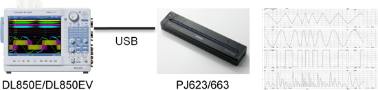
*Supported printers are Model PJ663/623 PocketJet 6 Plus. (Supplier: Brother Industries, Ltd.)
Powerful Real-Time Calculations and Analysis Functions
By default the ScopeCorder is equipped with a set of basic arithmetic mathematical functions such as addition, subtraction, division, multiplication, fast Fourier transformation and other computations. Furthermore to really enrich the measurement and analysis capabilities of a ScopeCorder, several real-time options are available.
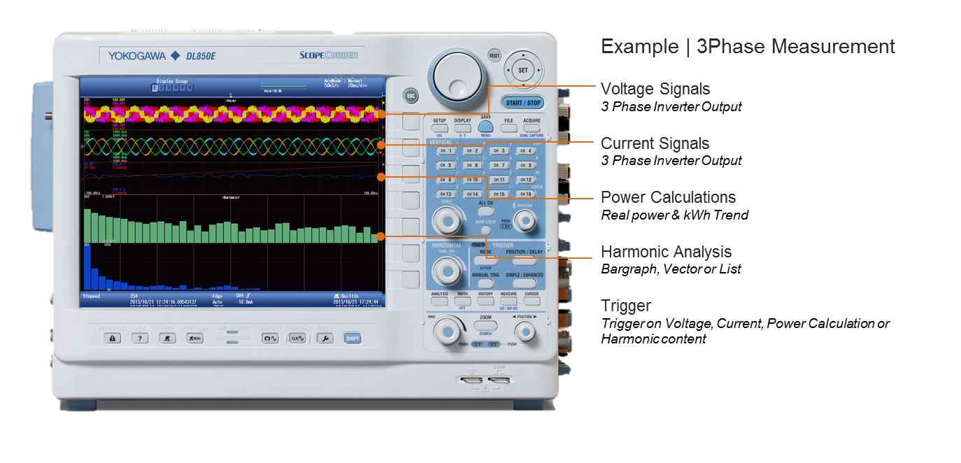
Real-Time Measurement of Electrical Power - /G5 option
Trend calculations such as active power, power factor, integrated power and harmonics, using a dedicated Digital Signal Processor (DSP) that is able to calculate and display up to 126-types of electrical power related parameters in real-time. This enables the user to display raw waveform signals such as voltages and currents along with power calculated parameters and even the capability to trigger on all of them. Data updating rate up to 100kS/s. Trend waveforms of each order of harmonics, bar-graphs and vector displays can be displayed. Both RMS and Power analysis modes are available. Besides the powerful power calculations, the /G5 option also contains all the functionality of the /G3 option.
Real-Time Mathematical Computations and Digital Filtering - /G3 option
Armed with a dedicated digital signal processor the ScopeCorder can perform mathematical calculations such as arithmetic operators with coefficients, integrals and differentials, and higher order equations on acquired measurement data. The results of these calculations are displayed during waveform capture in real-time. In addition to mathematical operators, steep digital filters can also be selected to isolate or trigger on the amplitude of certain frequency components.
User defined computations - /G2 option
With user defined computations it is possible to create equations using a combination of differentials and integrals, digital filters, and a wealth of other functions. Moreover it is possible to perform various types of FFT analysis using two FFT windows. In applications such as vibration and shock tests, you can easily evaluate abnormal vibrations while simultaneously measuring other signals.

Application Example | With FFT
Flexible operation and a variety of connection interfaces
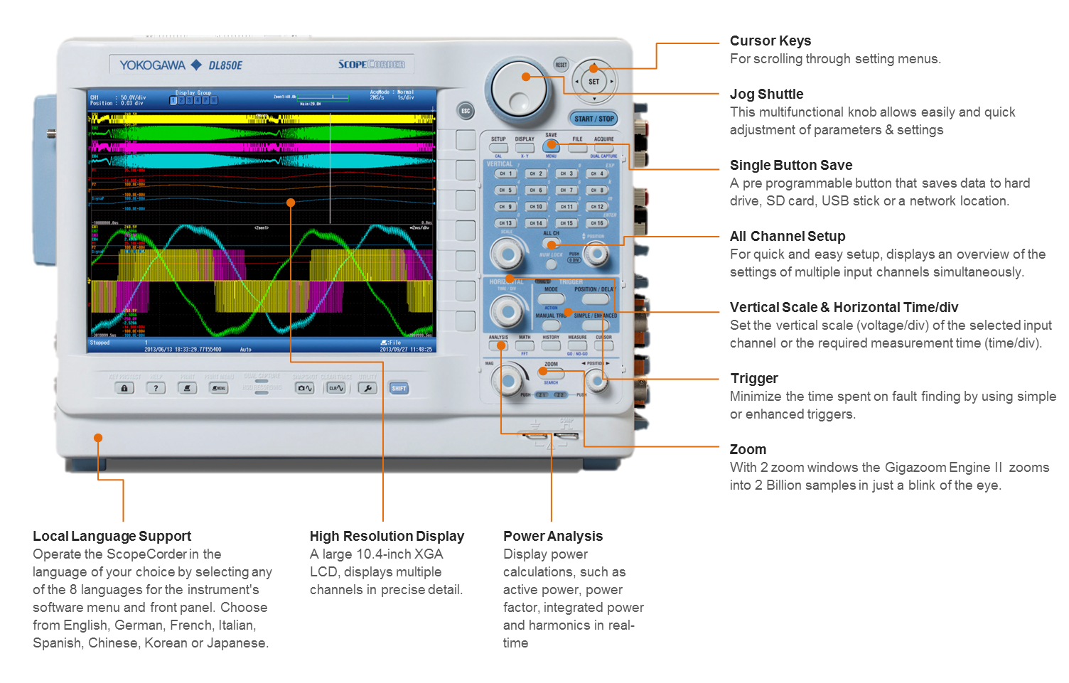
A ScopeCorder has been designed to grant users access to functionality in the field quickly and easily using the front panel menu buttons. For users that prefer workbench operation it is possible to connect a USB mouse or keyboard.
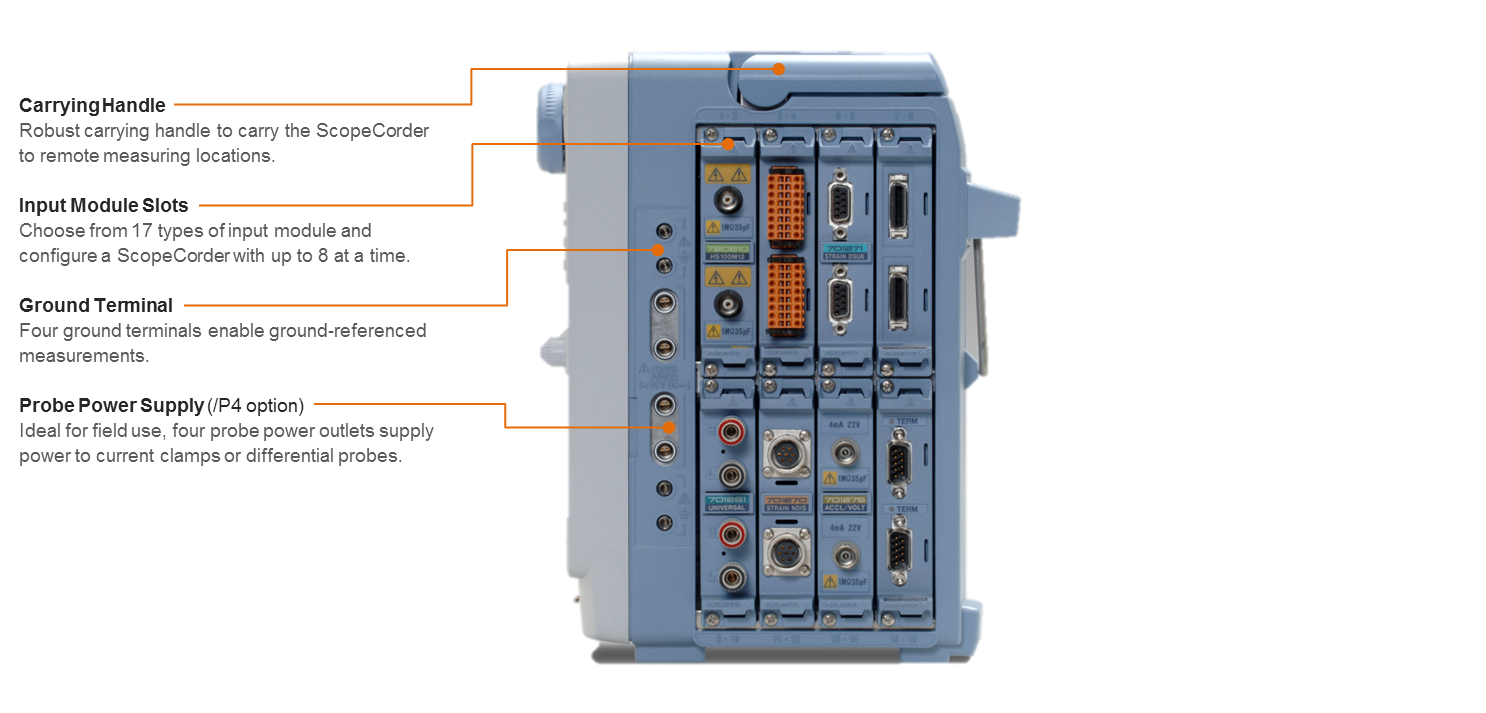
Front View
Left Side View
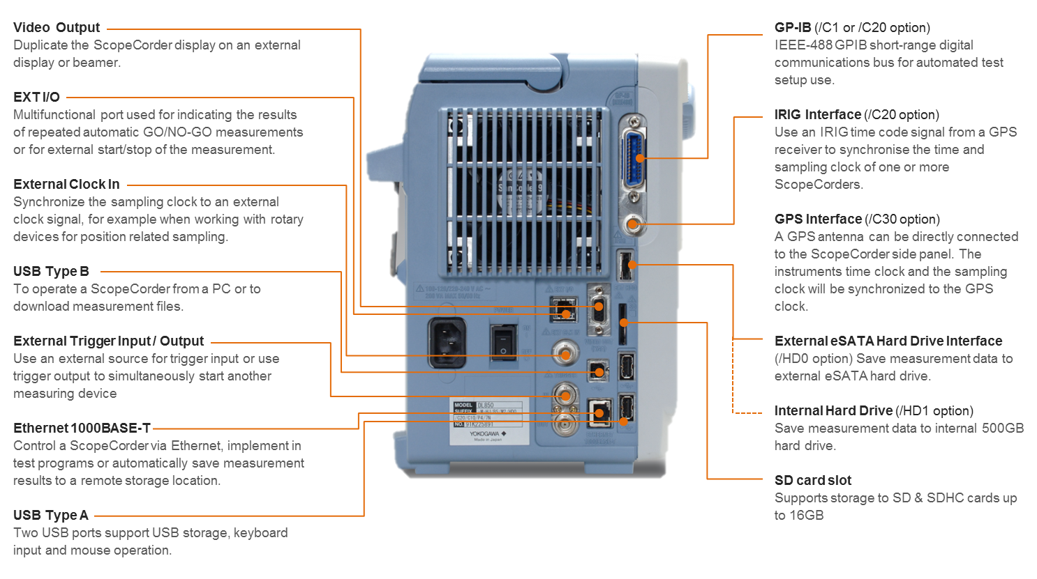
Right Side View
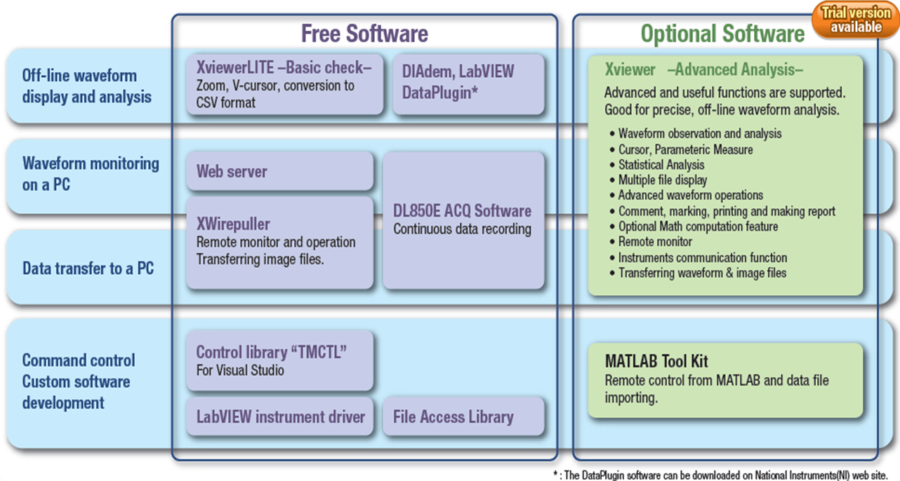
Software Control
Analyze measurement data using the ScopeCorder itself or on the PC using the Yokogawa Xviewer software or select any of the drivers below. Please download "free software" and "Trial Versions" in the software tab above.
The ScopeCorder Vehicle Edition is designed for engineers working in the automotive and railway industry. A common measurement challenge is to combine measurements of electrical signals, physical performance parameters, indicated by sensors, together with CAN- or LIN-bus data transmitted by the powertrain management system. A ScopeCorder Vehicle Edition addresses this requirement by providing a thorough insight into the dynamic behavior of the electromechanical system. The result is a considerable saving of time compared to other approaches such as analysis on a PC or the use of other software.

CAN and LIN Bus Monitoring
Use a ScopeCorder to decode the CAN or LIN-Bus signals and display information on physical data like engine temperature, vehicle speed and brake-pedal position as analog waveforms and compare this with the data coming from real sensors.

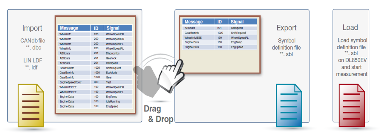
Symbol Editor
The symbol editor is a software tool which makes it possible to define which physical values from the CAN- or LIN-bus data frame have to be trended as waveform data on the display of the ScopeCorder. The Symbol Editor can accept vehicle-installed network definition files (CAN DBC, LIN LDF).
Battery Powered Operation - /DC option
In addition to AC power, it is also possible to take the ScopeCorder Vehicle Edition in a vehicle and power the unit from the vehicle's DC battery. The DC power option allows AC and DC power supplies to be used together to ensure a highly reliable power source. If the AC power goes down, the DL850EV instantly switches to the DC supply without interrupting the measurement.
-
DC power (10 - 18V)
-
AC power (100 - 120V / 200 - 240V)